
- Manufacturer Part Number : LTC4413EDD#PBF
- Manufacturer : AD
- Description : Dual 2.6A, 2.5V to 5.5V, Ideal Diodes in 3mm × 3mm DFN IC
- Series : LTC4413
- Reference Price : USD 1.72
- Our Price : We have a better price, contact us by email
- Product Type : PowerPath, Ideal Diodes & Load Switches
- Function : -
- Current Suggest : Recommended for New Designs
- Status : Production
- ROHS Status : ROHS Compliant (Lead Free)
- Package Type : 10-Lead DFN (3mm x 3mm w/ EP)
- Pins : 10
- MFG Package Case : 05-08-1699
- Part Type : OTH
- Standard Packing Type : Tube
- Standard Packing Quantity : 121
- Working Temperature : -40 to 125C
- Other Part Number : LTC4413EDD#PBF
- Shipping methods : DHL FEDEX UPS TNT
- Delivery Time : Ship within 1 day.
- Manufacturer Production time : 6-8 weeks (Normally have stocks)
- Weight : 0.001KG
Contact us to check the best price and real time inventory quantity for LTC4413EDD#PBF. If you need any more information about LTC4413EDD#PBF, you can also send us by email. Our email is [email protected], we will reply you in 12 hours.
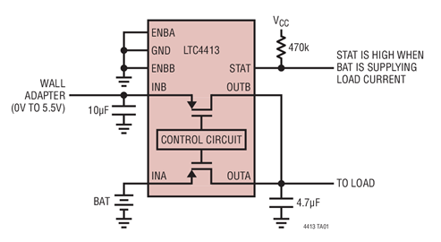
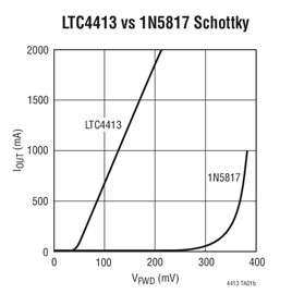
The LTC4413 contains two monolithic ideal diodes, each capable of supplying up to 2.6A from input voltages between 2.5V and 5.5V. Each ideal diode uses a 100mΩ P-channel MOSFET that independently connects INA to OUTA and INB to OUTB. During normal forward operation the voltage drop across each of these diodes is regulated to as low as 28mV. Quiescent current is less than 40μA for diode currents up to 1A. If either of the output voltages exceeds its respective input voltages, that MOSFET is turned off and less than 1μA of reverse current will flow from OUT to IN. Maximum forward current in each MOSFET is limited to a constant 2.6A and internal thermal limiting circuits protect the part during fault conditions.
Two active-high control pins independently turn off the two ideal diodes contained within the LTC4413, controlling the operation mode as described by Table 1. When the selected channel is reverse biased, or the LTC4413 is put into low power standby, a status signal indicates this condition with a low voltage.
A 9μA open-drain STAT pin is used to indicate conduction status. When terminated to a positive supply through a 470k resistor, the STAT pin can be used to indicate that the selected diode is conducting with a high voltage. This signal can also be used to drive an auxiliary P-channel MOSFET power switch to control a third alternate power source when the LTC4413 is not conducting forward current.
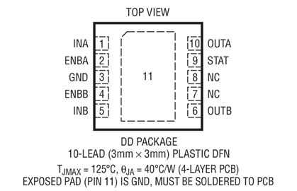
The LTC4413 is housed in a 10-lead DFN package.
| Features | |
| LTC4413 | Lower Iq |
| LTC4413-1 | Lower Vfwd, Faster Response, Higher Iq |
| LTC4413-2 | Lower Vfwd, Faster Response, Higher Iq, 13V (max) OVP |
Applications
- Battery and Wall Adapter Diode ORing in Handheld Products
- Backup Battery Diode ORing
- Power Switching
- USB Peripherals
- Uninterruptable Supplies
This product has been released to the market. The data sheet contains all final specifications and operating conditions. For new designs, ADI recommends utilization of these products.


